
Designed for Revive Medical Technology · Powered by INVENSOM-6UL SOM

🔬 Interactive PCB View · 📋 Project Assets · 🌐 Revive Medical Technology · 📜 License · 📝 Changelog
DermScope REVIVE is a pocket-size, high-speed embedded carrier PCB developed for handheld dermatology diagnostics. Designed as the motherboard/carrier for the INVENSOM-6UL System on Module, this board bridges cutting-edge medical imaging hardware with a compact, power-efficient form factor — enabling clinicians and dermatologists to perform real-time skin examinations in any environment.
💡 This carrier board hosts the NXP i.MX6UL ARM® Cortex®-A7 based INVENSOM-6UL SOM and routes its full peripheral set to a purpose-built medical imaging platform with multi-polarization dermoscopy optics, 2K touch display, and professional-grade camera pipeline.
|
🔝 Top Side
|
🔻 Bottom Side 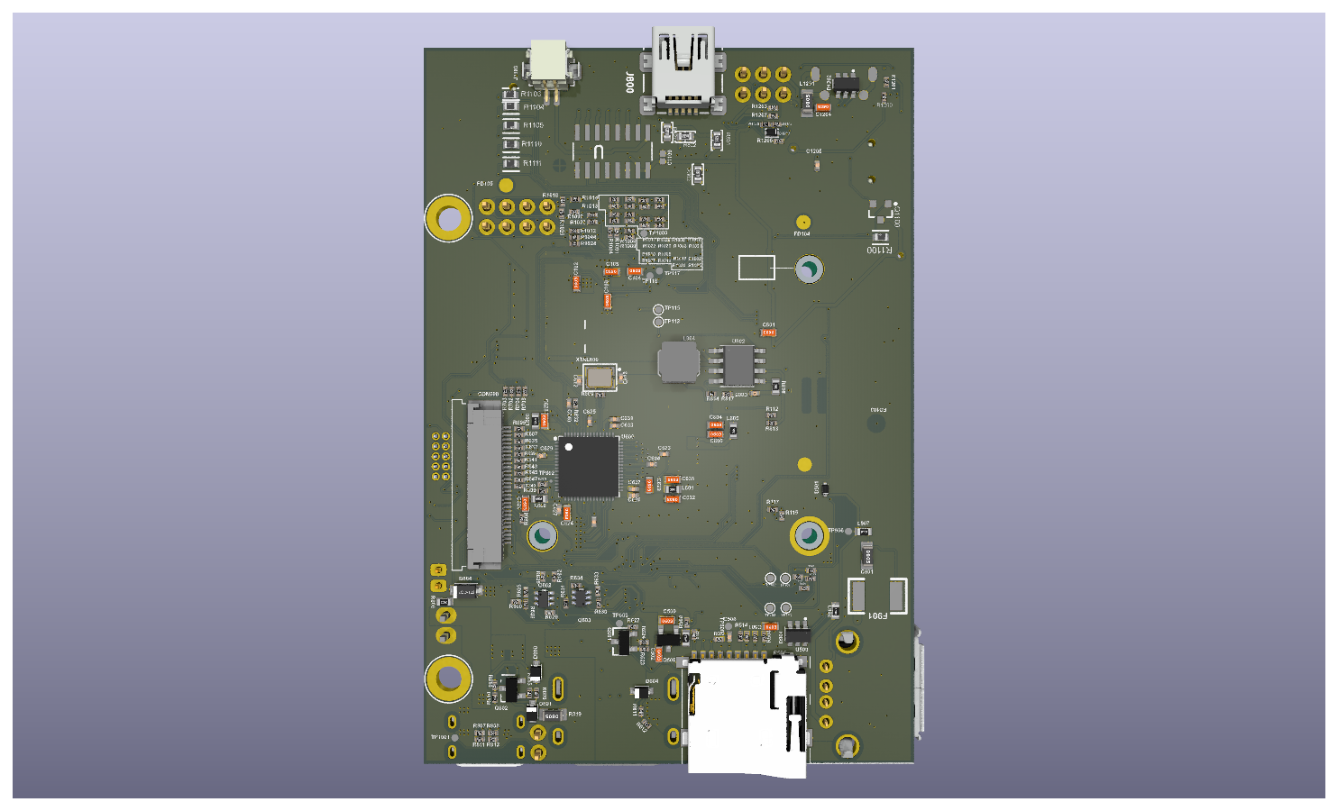
|
| Goal | Specification |
|---|---|
| 🩺 Medical Imaging | High-res skin capture with cross & linear polarization |
| 📷 Camera Pipeline | MIPI CSI 4-Lane interface to high-resolution image sensor |
| 🖥️ Display | MIPI DSI 4-Lane to 2K touch panel (LVDS & HDMI alternative outputs) |
| 🔋 Power | Rechargeable battery via TP4056, ≥ 2 hours runtime |
| 📦 Form Factor | Compact & handheld (board: 90 × 62 mm) |
| 🔒 Security | Hardware-rooted trust via INVENSOM-6UL ARM TrustZone |
| 🌐 Connectivity | Wi-Fi, Bluetooth, 4G LTE NB-IoT, GPS, Ethernet |
┌─────────────────────────────────────────────────────────────────────┐
│                        DERMSCOPE REVIVE CARRIER PCB                 │
│                                                                     │
│  ┌──────────┐    ┌────────────────┐    ┌────────────────────────┐  │
│  │ MICRO USB│───▶│  TP4056 CHARGE │    │     INVENSOM-6UL SOM   │  │
│  └──────────┘    │    MODULE      │    │  NXP i.MX6UL Cortex-A7 │  │
│                  └───────┬────────┘    │   up to 900 MHz         │  │
│  ┌──────────┐            │            │   1GB DDR3 / 2GB NAND   │  │
│  │ BATTERY  │──────┐     ▼            └──────────┬─────────────┘  │
│  └──────────┘      │ ┌────────────┐              │                 │
│                    │ │ OVER/REVERSE│   ┌──────────▼──────────────┐  │
│  ┌──────────┐      └▶│  VOLTAGE   ├──▶│     POWER SUPPLY        │  │
│  │ 15V 1x2  │        │ PROTECTION │   │     (+5V, EN)           │  │
│  └──────────┘        └────────────┘   └─────────────────────────┘  │
│                                                                     │
│  ┌─────── DISPLAY OUTPUTS ─────────────────────────────────────┐   │
│  │  MIPI DSI 4-Lane ──▶ DSI-to-HDMI/LVDS ──▶ MIPI DSI CONN   │   │
│  │                                       ──▶ HDMI 1.4 CONN    │   │
│  │                                       ──▶ LVDS CONN        │   │
│  └─────────────────────────────────────────────────────────────┘   │
│                                                                     │
│  ┌─────── CAMERA INPUT ────────────────────────────────────────┐   │
│  │  MIPI CSI 4-Lane ──────────────────────▶ MIPI CSI CONN     │   │
│  └─────────────────────────────────────────────────────────────┘   │
│                                                                     │
│  ┌─────── USB & STORAGE ───────────────────────────────────────┐   │
│  │  USB1 ──▶ OTG Micro USB                                     │   │
│  │  USB2 ──▶ USB HUB ──▶ 4× USB 2.0 Type-A                   │   │
│  │  UART2/UART4 ──▶ Selection Header ──▶ USB TTL Debug        │   │
│  │  SDIO2 ──▶ SD Card Connector                               │   │
│  └─────────────────────────────────────────────────────────────┘   │
│                                                                     │
│  ┌─────── ADC / GPIO / EXPANDERS ──────────────────────────────┐   │
│  │  eCSPI2 ──▶ MCP3208-B ADC (CH0–CH7) ──▶ ADC Connectors    │   │
│  │  GPIO_EXP 1–7 ──▶ GPIO Output Connector (Lens Interface)   │   │
│  │  GPIO_EXP 2–6 ──▶ GPIO EXT Connector                      │   │
│  │  I2C4 ──▶ J1102 Connector                                  │   │
│  │  UART3 ──▶ J1101 Connector                                  │   │
│  └─────────────────────────────────────────────────────────────┘   │
└─────────────────────────────────────────────────────────────────────┘
This carrier board is designed exclusively for the INVENSOM-6UL System on Module by Inventron.
| Category | Specification |
|---|---|
| 🧮 Processor | NXP i.MX6UL ARM® Cortex®-A7 @ 528 MHz (up to 900 MHz), 128 KB L2 cache + NEON™ MPE |
| 💾 Memory | Up to 1 GB DDR3 · Up to 2 GB NAND Flash · Up to 128 MB SPI NOR Flash (optional) |
| 📷 Camera | 8/10/16/24-bit Parallel CSI with BT.656 support |
| 🖥️ Display | 8/16/18/24-bit parallel LCD up to WXGA (1366×768) |
| 🔐 Security | ARM TrustZone, Secure Boot (HAB), AES-128/256, RSA-4096 DPA, TRNG, eFUSE (OTP), Secure RTC, Tamper Detection |
| 🌐 Ethernet | 2× 10/100 Mbit MAC + IEEE 1588 |
| ⚡ USB | 2× HS USB 2.0 OTG (up to 480 Mbps) with integrated PHY |
| 📡 Wi-Fi | 802.11 b/g/n, 65 Mbps (optional) |
| 🔵 Bluetooth | v4.2 BR/EDR/LE, 3 Mbps (optional) |
| 📶 Cellular | 4G LTE Cat M1/NB-IoT + 2G EGPRS fallback (optional) |
| 🛰️ GNSS | GPS, GLONASS, BeiDou, Galileo, QZSS |
| 🔌 Serial I/O | 5× UART · 4× I2C · 3× SPI · 2× CAN · 3× I2S · 8× PWM · 2× 12-bit ADC |
| 📐 Form Factor | 40 × 40 × 5.2 mm · 152-pin 1 mm pitch edge-castellated SMT |
| 🌡️ Operating Temp | −30°C to +70°C (standard) · −40°C to +85°C (no Wi-Fi) |
| ⚡ Operating Voltage | 3.4V – 4.2V (typ. 3.8V) |
- MIPI DSI 4-Lane → MIPI DSI to HDMI/LVDS converter
- HDMI 1.4 output connector
- LVDS display output connector
- VDD_3V3 and VDD_1V8 power rails for display logic
- MIPI CSI 4-Lane → High-resolution image sensor connector
- Supports RAW10/RAW12 capture for dermoscopy imaging
- Micro USB charging input
- TP4056 Li-Ion charge management module
- Over & Reverse Voltage Protection circuit
- Buck-up Battery backup rail
- ON/OFF Button and Reset Button
- VBAT and +5V regulated supply rails
- SDIO2 → SD Card connector
- Boot Mode and Boot Config jumper headers
- USB HUB → 4× USB 2.0 Type-A host ports (2× dual connectors)
- OTG Micro USB for device/host mode
- USB TTL debug via Selection Header (UART2 / UART4)
- UART3 → J1101 general-purpose connector
- I2C4 → J1102 expansion connector
- eCSPI2 → MCP3208-B 8-channel 12-bit SPI ADC
- CH0 & CH1 → ADC connector (J1103)
- CH2–CH7 → ADC_Conn expansion
- GPIO_EXP 1–7 → GPIO Output CON / Lens Connector (J1100)
- GPIO_EXP 2–6 → GPIO EXT CON (external LED/optics control)
| Parameter | Value |
|---|---|
| PCB Version | V2 |
| PCB Definition | Carrier Board |
| Board Thickness | 1.6 ±0.16 mm |
| Layer Count | 4 Layers |
| Board Size | 90 × 62 mm |
| Panel | 2×2 (5 mm stripe on edges) |
| Material | FR4 |
| Surface Finish | Immersion Gold (ENIG) |
| Min. Drill Diameter | 0.2 mm |
| Min. Via Pad Size | 0.4 mm |
| Outer Layer Line/Space | 4 mil / 4 mil |
| Inner Layer Line/Space | 4 mil / 4 mil |
| Via Plating Thickness | Min. 20 µm |
| Solder Mask | Top & Bottom · Color: Green |
| Silkscreen | Top & Bottom · Color: White |
| Impedance Control | ✅ Yes |
| RoHS | ✅ Compliant |
| Via Tenting | ✅ Yes |
┌─────────────────────────────────────────┐
│  TOP LAYER     │  CU     │ 0.035 mm (1.4 mil)  │
├─────────────────────────────────────────┤
│  PREPREG       │         │ 0.066 mm (2.6 mil)  │
├─────────────────────────────────────────┤
│  LAYER 1       │  CU     │ 0.035 mm (1.4 mil)  │
├─────────────────────────────────────────┤
│  PREPREG       │         │ 1.27 mm  (50 mil)   │  ← CORE
├─────────────────────────────────────────┤
│  LAYER 2       │  CU     │ 0.035 mm (1.4 mil)  │
├─────────────────────────────────────────┤
│  PREPREG       │         │ 0.066 mm (2.6 mil)  │
├─────────────────────────────────────────┤
│  BOTTOM LAYER  │  CU     │ 0.035 mm (1.4 mil)  │
└─────────────────────────────────────────┘
| Target Impedance | Layer | Trace Width / Gap |
|---|---|---|
| 100 Ω ±10% | TOP LAYER | 4 mil / 5.575 mil |
| 100 Ω ±10% | BOTTOM LAYER | 4 mil / 5.575 mil |
| 90 Ω ±10% | TOP LAYER | 4.495 mil / 4 mil |
| 90 Ω ±10% | BOTTOM LAYER | 4.495 mil / 4 mil |
| 85 Ω ±10% | TOP LAYER | 5.051 mil / 4 mil |
| 85 Ω ±10% | BOTTOM LAYER | 5.051 mil / 4 mil |
| 50 Ω ±10% | TOP LAYER | 4 mil (single-ended) |
| 50 Ω ±10% | BOTTOM LAYER | 4 mil (single-ended) |
⚠️ All high-speed signals (MIPI CSI, MIPI DSI, USB 2.0 HS, SDIO) are impedance-controlled. Reference layers: TOP → Layer 1, BOTTOM → Layer 2.
The carrier PCB is designed to fulfill the following product-level requirements for the DermScope REVIVE handheld dermatoscope:
- ✅ Compact, portable, and easy to carry
- ✅ Durable and field-ready construction
- ✅ Magnified, high-resolution skin image capture
- ✅ Rechargeable with ≥ 2 hours single-charge runtime
- ✅ High-resolution display (MIPI DSI / LVDS / HDMI)
- ✅ Onboard and expandable image storage (SD + NAND)
- ✅ Digital zoom functionality via iMX6UL GPU pipeline
- ✅ Cross and linear polarization switching via GPIO lens interface
- ✅ Smooth operation via Linux BSP on ARM Cortex-A7
| Component | Details |
|---|---|
| OS | Yocto Linux / Debian / Ubuntu |
| Kernel | Linux 4.9.11 |
| Bootloader | U-Boot 2017.03 |
| Security | OpenSSL, TLS/DTLS, Hardware Crypto Dev |
| Connectivity | Ethernet, Wi-Fi, BT, 4G/2G, GNSS drivers |
| IoT Protocols | MQTT, AMQP, CoAP, OPC-UA, LWM2M, oneM2M |
| Cloud | Microsoft Azure, AWS, Google Cloud |
| Graphics | Qt5, Wayland, XServer |
| OTA Updates | OS and Application update management |
This board was designed for Revive Medical Technology (RMT) — a US-based medical technology company focused on advancing diagnostic tools for dermatology and skin health.
PRJ-2026-PCB-0005-DERMSCOPE-REVIVE.github.io/
│
├── ASSETS/
│   ├── PRJ-2026-PCB-0005-DERMSCOPE-REVIVE.png       ← Top view (PNG)
│   ├── PRJ-2026-PCB-0005-DERMSCOPE-REVIVE.jpg       ← Top view (JPG)
│   ├── PRJ-2026-PCB-0005-DERMSCOPE-REVIVE bot.png   ← Bottom view (PNG)
│   └── PRJ-2026-PCB-0005-DERMSCOPE-REVIVE bot.jpg   ← Bottom view (JPG)
│
├── .github/
│   └── ISSUE_TEMPLATE/
│       ├── bug_report.md                             ← Bug report template
│       ├── feature_request.md                        ← Feature request template
│       ├── question.md                               ← Question template
│       └── config.yml                                ← Issue chooser config
│
├── index.html                                        ← Interactive PCB viewer
├── README.md                                         ← This file
├── LICENSE                                           ← Proprietary © RMT
├── CHANGELOG.md                                      ← Version history
└── CONTRIBUTING.md                                   ← Contribution guidelines
| Resource | URL |
|---|---|
| 🌐 Interactive PCB View | hiibrarahmad.github.io/PRJ-2026-PCB-0005-DERMSCOPE-REVIVE.github.io |
| 🏢 Revive Medical Technology | rmt-usa.com |
| 📦 INVENSOM-6UL SOM | Inventron |
| 📜 License | LICENSE |
| 📝 Changelog | CHANGELOG.md |
| 🤝 Contributing | CONTRIBUTING.md |
PRJ-2026-PCB-0005-DERMSCOPE-REVIVE
Designed with precision for Revive Medical Technology · Built on INVENSOM-6UL
© 2026 Revive Medical Technology. All Rights Reserved.